
Three Types of Database Design: A Complete Guide for Beginners
Database design
Database Design is a systematic approach that establishes how information is kept,
retrieved, and controlled.
In order to create a strong and effective database structure,it needs three main stages: conceptual, logical, and physical design.
Conceptual database design
The first stage, known as conceptual database design, determines the key data components, their connections, and related limitations. It serves as the basis for the logical and physical design phases that follow by encapsulating the organization's business principles in a high-level abstract model.
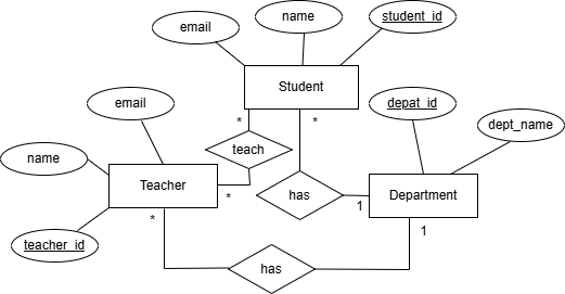
In particular, entities and their properties are identified using conceptual database design. Entities, like Student, are representations of actual things or ideas, whereas attributes, like Name and Student_ID, explain their characteristics.
The following procedures are commonly employed to put conceptual database design into practice:
- Gathering Requirements : To determine important data aspects, gather business requirements.
- Identify Entities and Attributes: Identify the main entities and the attributes that are related to them.
- Define Relationships: Explain the relationships between entities.
- Make an entity-relationship diagram using entity-relationship modeling.
- Review and Feedback: Consult stakeholders to validate the conceptual model and make necessary adjustments based on their suggestions.
Using Student, Teacher, and Department Entities as an Example
- Requirements Gathering
- Students enroll in departments.
- Teachers belong to departments.
- Teachers teach students.
- Identify Entities and Attributes
- Department_ID, Department_Name
- Student_ID, Name, Email
- Teacher_ID, Name, Email
- Define Relationships
- Department has many Students → one-to-many.
- Department has many Teachers → one-to-many.
- Teachers teach Students → many-to-many.
- Entity-Relationship Modeling
- Review and Feedback
- Finally, we discussed the final ER diagram with stakeholders to ensure it accurately reflects requirements and revised it as needed.
Logical database design
Logical database design is the process of creating a comprehensive data model that accurately represents an organization's data structure.
The following are the primary tasks involved in logical database design.
- Making a logical model out of the conceptual ER diagram.
- Establishing Primary and Foreign Keys are defined to enforce relationships between tables, and primary keys are assigned to uniquely identify records.
- To remove redundancy, apply normalization and arrange data into well-structured tables.
- Defining Data Types and Restrictions Decide on suitable data types.
- Business rules should be documented and converted into database constraints.
- Prior to physical implementation, review and validate the logical schema with the appropriate person to make sure it satisfies criteria.
Example:
- Mapping the Conceptual Model
- Student(Student_ID, Name, Email, Department_ID)
- Department(Department_ID, Department_Name)
- Teacher(Teacher_ID, Name, Email, Department_ID)
Teaching(Teacher_ID, Student_ID)→ to represent many-to-many relationship
- Defining Primary and Foreign Keys
Department_ID→ primary key in DepartmentStudent_ID→ primary key in StudentTeacher_ID→ primary key in TeacherTeachinguses a composite primary key: (Teacher_ID, Student_ID)
- Student.Department_ID → Department.Department_ID
- Teacher.Department_ID → Department.Department_ID
- Teaching.Teacher_ID → Teacher.Teacher_ID
- Teaching.Student_ID → Student.Student_ID
- Applying Normalization:Normalize all tables up to 3NF
- Specifying Data Types and Constraints
For Student:- Student_ID INT PRIMARY KEY
- Name VARCHAR(100) NOT NULL
- Email VARCHAR(100) UNIQUE
- Department_ID INT NOT NULL
- Department_ID INT PRIMARY KEY
- Department_Name VARCHAR(100) NOT NULL
- Teacher_ID INT PRIMARY KEY
- Teacher_Name VARCHAR(100) NOT NULL
- Email VARCHAR(100) UNIQUE
- Department_ID INT NOT NULL
- Documenting Business Rules:
- A student must belong to a department.
- A teacher must belong to a department.
- A student can be taught by multiple teachers, and vice versa.
- Examining and Verifying
- Give the necessary individual access to SQL definitions so they can verify the structure prior to implementation.
Note: A teaching table, also known as a junction table, links the primary keys of two related tables to simulate a many-to-many relationship.
Physical database design
Converting the logical data model into tangible structures that are tailored for a particular database management system is known as physical database design. It emphasizes performance, dependability, and scalability in the way data is stored, indexed, and accessed.
Important tasks for designing a physical database
- Table Structure Definition: assign suitable data types and provide column-level definitions to convert logical models into physical tables.
- Building Indexes: create indexes to improve query performance by accelerating the retrieval of data.
- Defining Constraints: Set rules like PRIMARY KEY, FOREIGN KEY, UNIQUE, NOT NULL, and CHECK to maintain data integrity.
Example:
- Define Table Structures with Data Types and Constraints:
- Implement a Many-to-Many Relationship Using a Junction Table:
- Indexing for Performance:
CREATE TABLE Department (
Department_ID INT PRIMARY KEY, Department_Name VARCHAR(100) NOT NULL
 );
CREATE TABLE Teacher (
Teacher_ID INT PRIMARY KEY,
Name VARCHAR(100) NOT NULL,
Email VARCHAR(100) UNIQUE,
Department_ID INT,
FOREIGN KEY (Department_ID) REFERENCES Department(Department_ID)
);
CREATE TABLE Student (
Student_ID INT PRIMARY KEY,
Name VARCHAR(100) NOT NULL,
Email VARCHAR(100) UNIQUE,
Department_ID INT,
FOREIGN KEY (Department_ID) REFERENCES Department(Department_ID)
);
 CREATE TABLE Teaching (
 Teacher_ID INT, Student_ID INT,
 PRIMARY KEY (Teacher_ID, Student_ID),
 FOREIGN KEY (Teacher_ID) REFERENCES Teacher(Teacher_ID),
 FOREIGN KEY (Student_ID) REFERENCES Student(Student_ID)
 );
 CREATE INDEX idx_student_email
 ON Student(Email);
 CREATE INDEX idx_teacher_email ON Teacher(Email);
 CREATE INDEX idx_teaching_teacher
 ON Teaching(Teacher_ID);
 CREATE INDEX idx_teaching_student ON Teaching(Student_ID);
Latest Posts

Top 9 Web hosting Companies in Ethiopia.
LetUsLearn
May 28, 2025

File Handling in Java.
LetUsLearn
May 28, 2025

Online Communication Platform for Teachers and Students.
LetUsLearn
May 28, 2025

I’m committed to providing tailored solutions and always ready to assist if any issue arises.
LetUsLearn